If you are concerned about RF Radiation from your smart meter or have electro-sensitive people in your home, there is something you can do to lessen the RF that comes from the meter. A Faraday cage blocks electrostatic and radio frequencies. So we can build one that fits right over the transmitting part of the meter and it will still work and keep you safer and let the electric company still receive their data. How? Keep reading.
Step 1: Supplies Needed
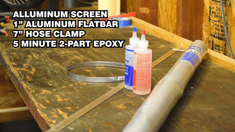
These are Amazon affiliate links to products like those used in this project where I get a small percentage from the sale. Feel free to shop them yourself at a big box store or whatever if you don't want to use these links:
Step 2: Create the Circle Template
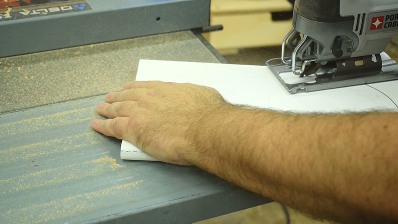
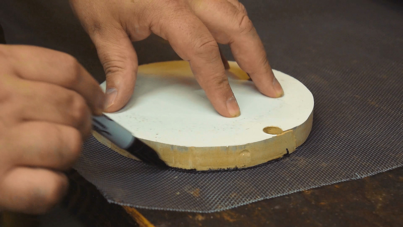
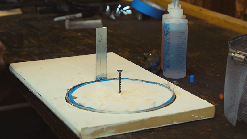
I used a scrap piece of MDF and and compass to draw a 7" circle on it. I then drilled a hole and used a jigsaw to cut the circle out. We will use this circle to help us bend and hold the flatbar into a ring.
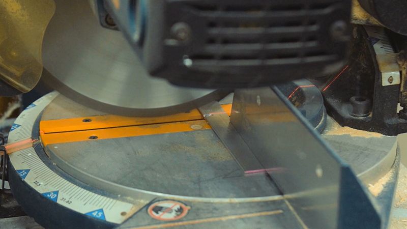
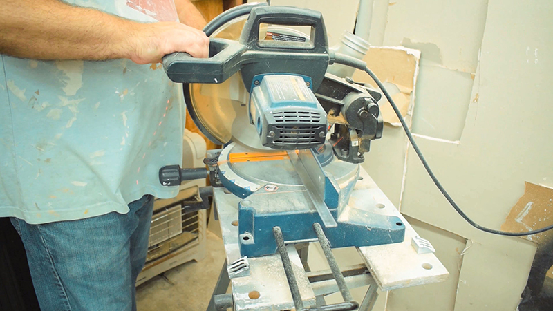
Mark a 5" length on the flatbar and cut it on the miter saw. You can cut this thin aluminum on just about any kind of saw. Even a handsaw. This piece is for the spine of the shield.
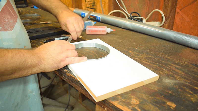
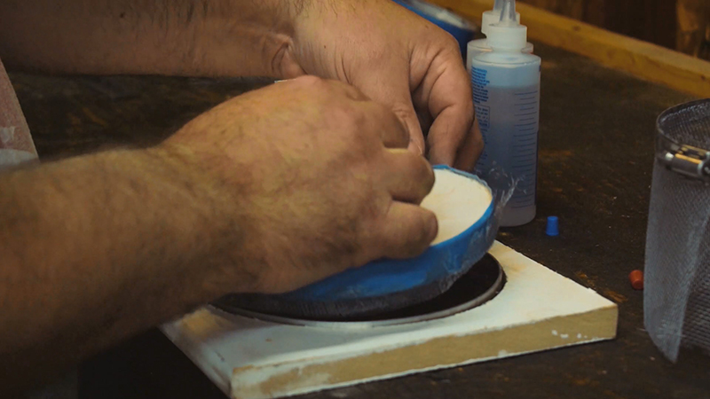
Take the rest of the flat bar and gently bend it into the wooden template hole. It should be too long and that is ok, we are going to mark it just a little short of the other end and then take it back out of the form and cut it at the mark. Then put it back into the form and it should fit with a little gap.
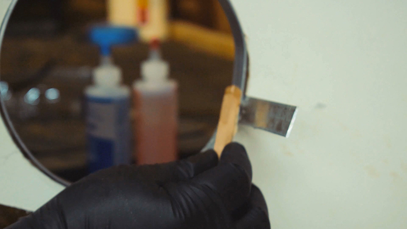
Mix up some 5 minute epoxy and add it to the spine and ring at the joint. Use plenty to make it strong. Put that aside to cure.
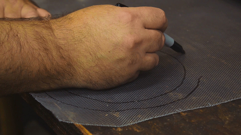
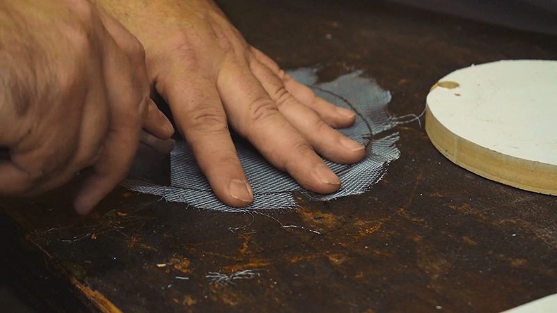
Use the offcut of the form and draw a circle on a piece of aluminum screen. Then freehand a larger circle around that one leaving about an inch between the smaller circle and the larger one. Cut out the LARGER circle. Then cut triangle notches around the screen. This will leave "tabs" to fold up when it is placed within the ring. Be sure not to cut the notches past the inner circle line.
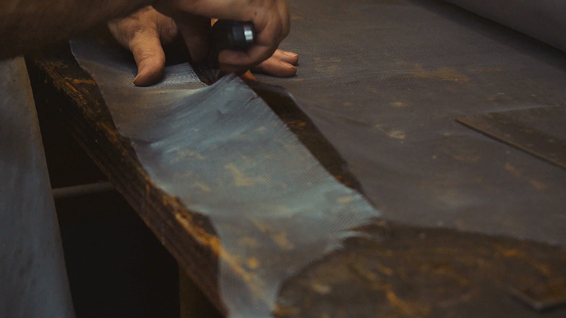
Now mark and cut a strip of screen about 5" wide and long enough to go all the way around the hose clamp and overlap by a few inches.
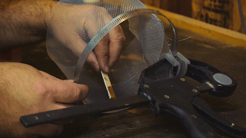
Clamp one end of the screen to the hose clamp close to the tightening screw, but not too close. You absolutely do not want to put the epoxy near the moving parts of the clamp because if you do, it will glue it to that position and will not be adjustable. Be aware of that. Once clamped, mix up some 5 minute epoxy and spread it on the screen and hose clamp starting from the clamped end. Only mix up enough to do a few inches because it is very difficult to hold that floppy strip of screen into that ring and get sticky epoxy in the right places. If you just start with a small part of one end and let that cure, it gives you a good solid end held in place so it won't flop around as much.
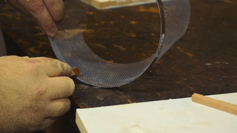
Once that is cured, mixed up more epoxy and go all the way around the hose clamp being sure to stop before you get to the part that has to move when you turn the screw.
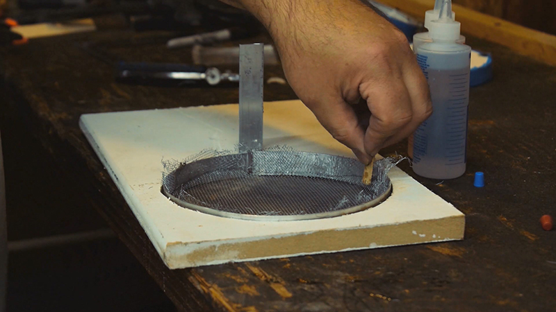
Wrap the offcut with masking tape. Cover the ring with epoxy and push the top screen piece (the one with the tabs) into it using the offcut. DO NOT LET IT CURE COMPLETELY. After just a couple of minutes when the epoxy just starts to cure, pull the offcut out (I put a screw into it partially to use as a handle). Pull it out carefully so the screen won't come with it. Then you can straighten and get the screen set while it fully cures.
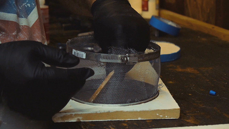
Add more epoxy around the ring and put the sides into it (with the hose clamp at the opposite end of the ring). Also use epoxy on the spine to connect it to the hose clamp for stability.
IMPORTANT: The screen MUST overlap a couple of inches or so to get a good solid shield. I put my overlap right where the adjustment screw is on the hose clamp so it could move when adjusted.
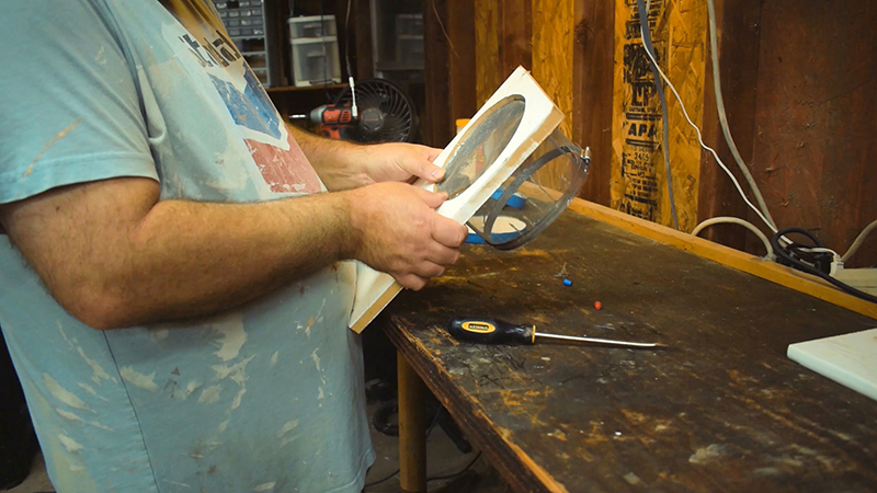
After it is fully cured, pop it out of the form. You might have to use a flat head screwdriver to losen any little areas that epoxy might have gotten on between the ring and the form. Then it should just push right out.
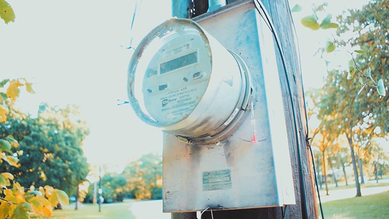
Slide it over the glass part of the meter which is where the RF Transmissions are sent. Get it on all the way to the box or as far as you can get to block as much as possible. Then tighten the adjustment screw on the hose clamp. Don't over tighten but just get it snug enough so it won't slide off.
You are now blocking RF Frequencies by about 95% or a little more by my tests.
QUESTION: Will the electric company be mad at me for blocking their meter?
ANSWER: No. In the vast majority of cases, the meter is way overpowered for what it needs. The 5% or so that still gets through is enough for the meter to communicate with what it needs to work just like it was. The electric company will not even see a difference in the majority of cases.
Watch me build one...